This post is part 4 of a series covering material I presented in a talk at PyCon 2019.
In the previous parts of this series, I covered what a PLC is, and how PLCs are programmed. In industry, the Python developer is usually not involved in the purchasing, installing, and programming of a PLC. If you find yourself working with PLCs in academia or for a hobby project, you might actually be the one doing these things yourself. Either way, I assume that you somehow found yourself with a programmed PLC and now want to connect to it using Python.
Modbus: Two PLCs talking to each other
A PLC by itself is great for controlling a single machine or even a small production line. Just wire all the sensors and actuators to the PLC’s I/O terminals and put a program on the PLC. However, since the early days of PLCs, there has been a need to control larger systems such as HVAC in large buildings or long production lines. To do this requires either PLCs talking with each other or to a central point of coordination.1
Modbus is a communication protocol to address this need that was invented soon after the first PLCs. (The name “Modbus” derives from the company name Modicon, the inventors of the PLC.) Today, many other protocols exist to serve the same and similar purposes and I will cover some of them in the next post of this series. Despite, or maybe because of, being a rather primitive protocol, Modbus is still widely used today. It’s also an open standard and virtually universally supported in PLCs and with libraries in many programming languages including Python. Enough reasons for me to use it when demonstrating the connection of Python and PLCs in my conference talks!
What do we need to know about Modbus?
The key point is: Modbus allows read-write access to PLC program variables2 over Ethernet or Serial. If you’re in a rush, you can step reading now. Seriously. Everything below are details on how to do this accessing of variables over Ethernet3.
Modbus is a server/client protocol, i.e. unidirectional. The protocol dates itself by using the “master/slave” terminology to refer to these roles. The server, or “slave”, is the entity that maintains a list of variable values and allows other entities to change them through network requests. The client, or “master”, are those other entities which send network requests in order to read or write the values of variables stored in the server.
Instead of variable names, Modbus uses register addresses to identify the variables on the server. The register address space is divided into four groups. Each group is defined by the data type that can be stored in it and its read/write permissions.
| Address range | Data type name | Data size | Access |
|---|---|---|---|
| 00001 - 09999 | Coil | 1 bit | Read-write |
| 10001 - 19999 | Discrete input | 1 bit | Read-only |
| 30001 - 39999 | Input register | 16 bits | Read-only |
| 40001 - 49999 | Holding register | 16 bits | Read-write |
All PLC programming software tools that I have seen guide you through this and won’t let you assign an incorrect address.
The Modbus protocol defines a collection of message formats for reading and writing registers, either one-at-a-time or in groups. When using an existing Python library (like we do below), there is no need to know the details about those. But if you’re curious, the Wikipedia page about Modbus has an absurd amount of detail on the command types.
As I mentioned above, Modbus was invented to allow two or more PLCs to communicate with each other. When you use a Python library to make a laptop (or server or RaspberryPi or whatever other device you run your Python code on) send Modbus commands, you are basically emulating that “second” PLC. Since Modbus has no authentication or user agent headers or anything like that, your “first” PLC can’t tell if another PLC or a laptop is sending Modbus commands to it.
In the example below I am going to change a time interval, measured in hundredths, by sending a Modbus message from my laptop to the PLC. Numbers require more than one bit to store and I want to write it, not just read, so I will be using a register address in the 40,000 range.
Before we can write any values over the network, we’ll have to tell the PLC which piece of information to store in which of the Modbus register addresses. Let’s do that next.
Setting up the variables
Enabling the Modbus server and configuring which PLC program variables to make available through Modbus works differently for each brand of PLC. Hopefully, the information is right there in the help menu or manual. If you are unlucky, your PLC vendor will make you pay an extra license fee for the Modbus functionality.4
Here’s how it works in the Automation Direct Productivity software by example of the pedestrian crossing traffic signal demo from the PyCon presentation. Skip to the next heading if you want to jump right to the Python part. If you want to follow along, the ladder logic of the example is on Github, you can download the Productivity software for free here, and you can watch me talk through it starting at 16:10 in the Youtube recording.
A prerequisite for configuring a variable to be available through the Modbus server is to use variables in the first place. Here is one example of a ladder logic block referencing a variable instead of a fixed numerical value:
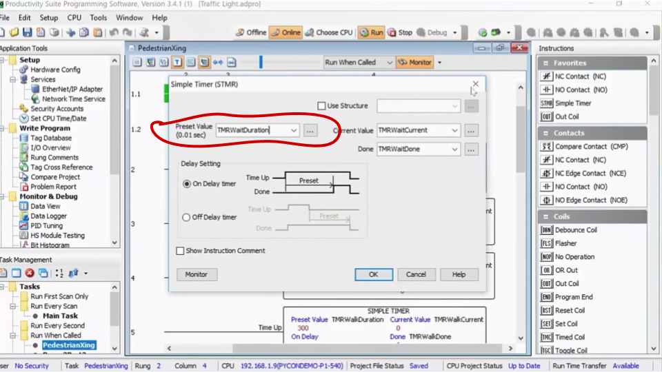
A Timer block in a ladder logic program with the timer duration set to the variable `TMRWaitDuration` (instead of a fixed numerical value). Screenshot from my Pycon 2019 presentation.
Once variables are in use for all relevant values in the ladder logic program, you can head to the “Tag Database”. This is a table listing all variables used in the entire ladder logic program with a bunch of information about each variable such as the initial value (on PLC startup) of the variable and its data type. In the following screenshot you can see how I used the “Mod Start” and “Mod End” columns to assign Modbus register numbers to six of the variables in my program.
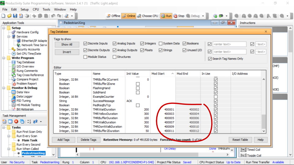
The Tag Database popup showing six ladder logic variables being assigned Modbus registers. Screenshot from my Pycon 2019 presentation.
At this point, there is a PLC that is configured to store some of its internal variables in Modbus registers that can be read and written to over the network.
If you are following my example of the pedestrian crossing traffic signal, we have the waiting time between pressing the pedestrian request button (aka “beg button”) and the car signal turning yellow in holding register 40001 and 40002 (two registers because it’s a 32 bit variable and registers are 16 bits).
pymodbus as Modbus client
pymodbus is an actively maintained and popular (by download count and Github stars) implementation of the Modbus protocol in Python. Pip-install it and your laptop will suddenly be fluent in PLC lingo!
pip install pymodbus
The following script uses the most basic function of pymodbus to synchronously read a range of 12 holding registers from a PLC located at IP address 192.168.1.9 on the network.
from pymodbus.client.sync import ModbusTcpClient

PLC_IP = "192.168.1.9"

client = ModbusTcpClient(PLC_IP)
print(client.read_holding_registers(0, 12))
This outputs:
[500, 0, 300, 0, 100, 0, 300, 0, 700, 0, 50]
Your results will look different if you are running a different program, of course. Based on my PLC configuration, the various timer intervals in my traffic signal program are:
| PLC Variable | Description | Value |
|---|---|---|
TMRWaitDuration | Time between ped. button press and yellow | 5000ms |
TMRYellowDuration | Time between yellow on and red on | 3000ms |
TMRBufferDuration | Time between red on and walk on | 1000ms |
TMRWalkDuration | Time walk signal is visible | 3000ms |
TMRDontWalkDuration | Time flashing hand is visible | 7000ms |
TMRBuffer2Duration | Time between | 500ms |
As mentioned above, the variables in my ladder logic program are in units of hundredths of seconds. And all my variables are 32 bit integers covering two Modbus holding registers, explaining the zeros in every other register.
Note that in the read_holding_register() method call I didn’t have to write out the 40001 holding register address.
Instead, the function expects a start index and read length (in registers).
To read the first twelve holding registers, call read_holding_register(0, 12) and pymodbus figures out which address that is.
Personally I find the weird mixing up of 1-indexed PLC configuration and 0-index Python library annoying, but c’est la vie when using 50 year old communication protocols.
Similar methods exist for reading the other Modbus data types: read_coils(), read_discrete_inputs(), read_input_registers().
In most situations, this is where you stop. Reading variable values from the PLC at periodic intervals and storing them in a time series database is basically what buzzwords like “IIoT” (Industrial Internet of Things) and “Industry 4.0” are about.
But remember that Modbus also let’s us write (some) register values!
Continuing with my example above, I would like to reduce the wait time between pressing a pedestrian button and the traffic light turning yellow to 100ms.
Why would pedestrians have to wait any longer than that anyway?
Here is the pymodbus snippet for changing 32-bit integer stored in the first two holding registers (40001 and 40002):
# continued from above
client.write.registers(0, [10, 0])
print(client.read_holding_registers(0, 12))
This outputs:
[10, 0, 300, 0, 100, 0, 300, 0, 700, 0, 50]
Compare the output to the previous snippet, et voila, you see that the register value is updated to 10 for 100ms.
In the PyCon talk recording you can watch me try out if the traffic light really switches to yellow faster at 19:10 (spoiler: it works).
Of course, things get really interesting when the Python code pulls variables from the PLC, does some kind of computation on them, and then writes the output back to the PLC. Doing so raises interesting questions about which part of a system’s control logic should be implemented in ladder logic on the PLC versus in Python on another compute device. That’s material for a future post.
pymodbus as Modbus server
For the sake of completeness, one more thing to close this post out: In the example above, pymodbus was used as the Modbus client (or “master” in Modbus lingo), reading and writing Modbus variables stored in the PLC. It is also possible to flip this around: Use pymodbus to make your Python code act as server (or “slave” in the Modbus lingo) and have the PLC read and write variables on your laptop/server/etc. I doubt that this gets used a lot in the real-world because it requires changing the ladder logic program to send Modbus commands. And if you can change the ladder logic on your PLC, you probably have further, better, options available than send Modbus commands… One reason one might set up their system with the PLC as Modbus client is that it enables event based logging instead of periodic polling. For example, with my traffic signal I could set up the PLC to change Modbus variable on my pymodbus-based Modbus server whenever the light changes.
Footnotes:
The terminology around this is muddy at best, but SCADA and DCS are often used to talk about the difference between centrally controlled and distributed control systems. ↩︎
PLC program variables are often called “tags”. Because this post is written as an introductory explainer for Python programmers, I’ll stick with the “variable” terminology. ↩︎
For my conference talk demos I usually use the TCP version of the Modbus protocol because I have spent too many hours of my life troubleshooting USB-to-RS232 converter problems already. ↩︎
While I have never seen a vendor charge extra for Modbus functionality, I have seen it for other industry-standard communication protocols. ↩︎