This post is part 2 of a series covering material I presented in a talk at PyCon 2019.
I have prepared three different conference talks about PLCs for Python programmers. Annoyingly, you can’t assume that every Python programmer knows what a PLC is, so I always have to sacrifice a few minutes of my time slot1 to convey the basics before diving into my actual topic. This blog post is the content I have settled on for those first five minutes of my talks.
In the most general sense, PLCs are just another type of computing device. There are laptops, smartphones, gaming consoles, …, and there are PLCs. Each class of device is optimized for a specific application; PLCs are optimized for operating at the interface between the world of computing with bits and bytes and the physical world of electrons and atoms.
The acronym PLC stands for Programmable Logic Controller. But this hasn’t always been the case, there’s an interesting bit of trivia about the acronym: When PLCs were invented in the 1960s, they were simply called “Programmable Controller” or “PC”. In the 1980s the personal computer became a big deal and also used the acronym PC, prompting the Programmable Controller people to add a “Logic” to the name of their PC, coining the term PLC still in use today.
You might wonder where these PLC things are hiding if they have been in existence since the 1960s and, allegedly, are still worth giving conference presentations about today. To answer this pointed question, I created this collection of slides where a stock photo is annotated with beautiful red-yellow Powerpoint arrows to annotate where PLCs are hiding:2
The examples covered in those slides are all types of machine or infrastructure where PLCs are commonly used: Assembly lines in factories, standalone factory equipment, wind turbines, construction cranes, amusement park rides, automated car washes, escalators, elevators, trains, HVAC and building control systems, oil rigs.
And this is what a PLC looks like. It’s a stock photo but it contains the important parts: A box with a few LEDs and lots of wires connected to it.
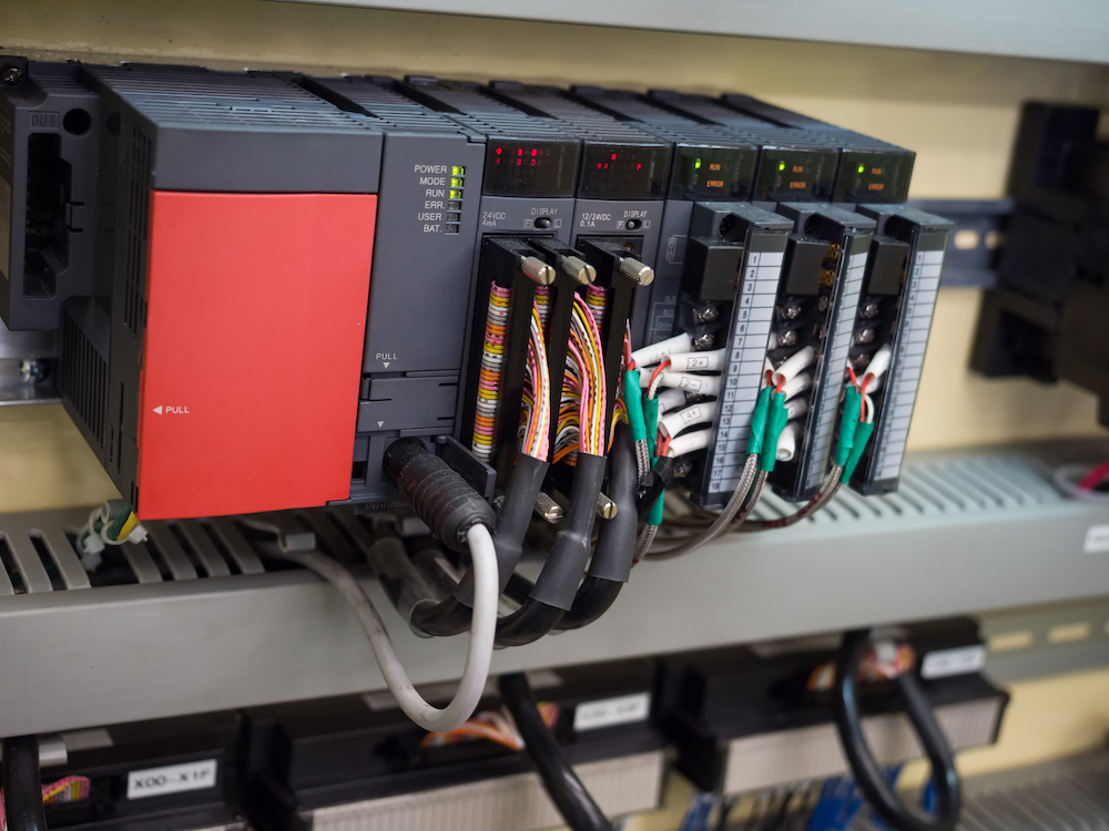
Stock photo of a Programmable Logic Controller (PLC)
Those colorful wires connect to the “field devices”, a fancy term for sensors and actuators. Let’s do a quick crash course on field devices!
Sensors are devices that measure an observable phenomenon in the physical world and turn it into an electrical signal (which will then become a variable in the PLC logic). Actuators are the inverse: The take an electrical signal (which started out as a variable in the PLC logic) and convert it into an effect on the physical world. If you consider an elevator, the buttons inside the cabin and the light curtain in the door are sensors; the motor that opens and closes the door and the speakers that plays a chime when the elevator arrives at the destination floor are actuators (to name just a few examples).
The electrical terminals on the PLC where the wires are connected to are often called “I/O”, for “inputs and outputs”. There exist many different types of electrical signals, in part due to the challenges of physics and in part due to the challenges of standardization. Many PLCs on the market are modular so that you can purchase I/O modules to match exactly the kind of electrical signals you need to match the sensors and actuators in your application. For example, you might purchase a PLC I/O module for digital sensors that use a 4-20mA current loop electrical signal. Other sensors might use analog voltages or even RS-232 serial signals, and there are PLC I/O modules for that too. Not every PLC is modular in this way, but many products on the market today are.
If you look carefully at the PLC in the stock photo above, you can see that it consists of several modules. The key point to remember about all this signals stuff is that some signals are digital and some analog. Digital I/O is for physical phenomena that are either on or off, the electrical signal therefore being either high or low, and we’ll want to use a boolean variable to reference the signal. Analog I/O represents a continuous physical phenomenon, the electrical signal needs to be measured with some resolution, and we’ll want to use a numeric data type to reference the signal. In my presentations I use the slide below to illustrate these points.
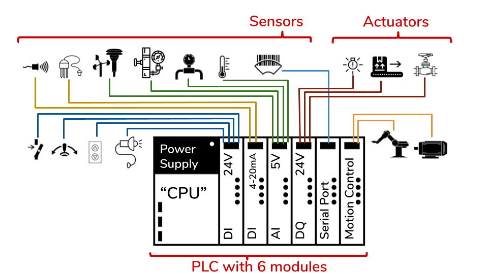
Example schematic of a PLC with six different I/O modules to connect to various types of field device
The hypothetical PLC in the example contains six different types of I/O module: Digital inputs (abbreviated DI), analog inputs (abbreviated AI), and digital outputs (abbreviated DQ). That’s not a typo, the letter Q has somehow become the defacto standard for abbreviating “output”, probably to avoid possible mixups between the letter O and the number 0. You’ll see DI, AI, DQ, and AQ again in variable names in later parts of this series of posts.
Finally, it’s time to talk about what the PLC actuall does. Like every computing device in the world, it executes an Input-Process-Output (IPO) cycle.
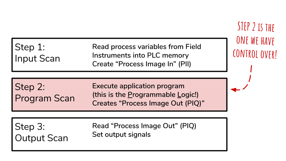
Input-Process-Output. The PLC runs this cycle indefinitely. The second step is the programmable one.
First: Inputs. Using signal processing electronics, the electrical signals from field devices are read and converted into variables which are stored in a section of memory traditionally called “Process Image In”. Second: Processing. This is where the PLC executes the programmable logic. Usually, the logic is written to turn the input variables into output variables using math or rules. The output variables are written back into memory into an are traditionall called “Process Image Out”. Third: Output. Again using signal processing electronics, the PLC turns the value from memory into the corresponding electrical signal. And then the cycle begins again.
In the old days, PLCs were built from special purpose electronics. Today’s PLCs are general purpose processors that become PLCs by virtue of the software running on them. You can even turn a Windows PC into a PLC by installing a “Software PLC”. I will cover this in more detail in later parts of this series. But first, let’s look at how PLCs are programmed (spoiler: it’s not Python).